Introduction
Bridge scour destroys foundations before any visible damage appears above the waterline. According to FHWA, scour is the leading cause of bridge failures in the United States — and an analysis of 12 states found that 60% of bridge failures from 1966 to 2005 resulted from scour. By the time visible damage appears, the structural damage is often already done.
For engineers, contractors, and municipalities managing Iowa's stream crossings and bridge infrastructure, one flood event can undermine a foundation entirely. Spring snowmelt and storm runoff create aggressive hydraulic conditions that accelerate this process — often faster than inspection cycles can catch it.
This guide covers what you need to assess and address scour risk:
- What scour is and why it threatens infrastructure
- The three distinct types engineers must design for
- Common protection methods and materials
- The critical role of geotextile filter layers
- How to monitor scour development at bridges
- How to select the right protection system for your project
Key Takeaways
- Scour causes more U.S. bridge failures than any other factor — armor without a geotextile filter underneath will fail
- Local, contraction, and long-term degradation scour can all act simultaneously at a single crossing
- Effective protection is always a system: geotextile filter + sized armor + proper edge treatment
- FHWA's HEC-18 and HEC-23 are the controlling frameworks for evaluation and countermeasure design
- Iowa DOT defines five revetment classes — match your stone selection to those specifications
What Is Scour and Why Does It Matter for Civil Infrastructure?
Scour is the erosion and removal of streambed or bank sediment around the base of a structure — a bridge pier, abutment, culvert, or offshore foundation — caused by the force and turbulence of flowing water.
When flowing water hits a solid obstruction, it accelerates around the edges and dives toward the bed, forming horseshoe vortices and wake vortices that act like underwater drilling machines. These vortices progressively excavate sediment, creating scour holes that deepen with each high-flow event.
The structural consequences:
- Foundations lose lateral and vertical bearing support as sediment is removed
- Settlement and tilting follow, often before any above-water sign appears
- In severe cases, sudden collapse occurs with no visible warning
FHWA's Bridge Technologies page continues to identify scour as the leading cause of bridge failures in the U.S. — not an occasional contributor, but the top cause. A peer-reviewed ASCE study found flood and scour together contributed to nearly 53% of all U.S. bridge failures in its dataset, reinforcing the scale of the problem.
Scour in a Construction Context
That failure risk doesn't wait for a finished structure. During active construction, scour exposure is often at its peak. Temporary works, newly placed foundations, culverts, and stream crossings are all exposed before permanent protection is installed. A single high-flow event during construction can undermine a pier before the riprap layer is even placed. Scour protection planning needs to start at the design stage, before any concrete is placed.
Types of Scour: Understanding the Different Forms
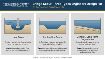
FHWA HEC-18 defines scour as the erosive action of flowing water that excavates and carries away material from stream beds and banks. The key point for design: total scour at a bridge is the sum of three distinct components, and all three can act simultaneously.
Local Scour
Local scour is the concentrated erosion directly around individual structures — bridge piers, abutments, and spurs. It's driven by the horseshoe vortex that forms at the base of a pier and the wake vortices that trail downstream.
This is the most commonly addressed scour type in bridge design, yet local scour holes can reach significant depths during a single flood event, then partially refill with loose sediment as flows recede — making post-flood visual inspection unreliable without probing.
Contraction Scour
Contraction scour occurs across the entire channel width when a bridge crossing, embankment, or natural channel constriction reduces the flow area. The reduced cross-section accelerates flow velocity and increases bed shear stress uniformly across the contracted section.
Where local scour targets the area around a single pier, contraction scour lowers the entire channel bed at the crossing. That distinction is critical for abutment design: even a well-protected pier can fail if contraction scour drops the surrounding bed below the abutment's embedment depth.
General Scour : Long-Term Streambed Degradation
General scour is the long-term, gradual lowering of the streambed over time. Causes include:
- Changes in upstream sediment supply (dam construction or removal)
- Channel straightening or channelization
- Altered watershed hydrology from land use changes
- Gravel mining within the channel
General scour compounds the risk from the other two types. A bridge designed with a 6-foot local scour depth allowance can fail prematurely if the bed has already degraded 4 feet from long-term trends. HEC-18 explicitly requires engineers to evaluate watershed and channel trends before sizing countermeasures.
Common Scour Protection Methods and Materials
Selecting a scour countermeasure means matching the material's hydraulic resistance to site-specific conditions: flow velocity, channel geometry, and the type and scale of structure being protected. FHWA HEC-23 is the controlling reference for countermeasure selection and design.
Riprap and Rock Armor
Riprap — angular, durable rock placed around piers, abutments, or streambanks — is the most widely used scour countermeasure. It works by absorbing and dissipating flow energy before it can erode the underlying bed.
Advantages: widely available, familiar to contractors, cost-effective for most sites.
Design considerations per HEC-23:
- Pier riprap is sized using a rearranged Isbash equation based on local design velocity
- Abutment riprap uses equations based on Froude number and setback ratio
- Three failure modes to design against: shear failure, winnowing failure, and edge failure
Iowa DOT defines five revetment classes based on aggregate size — always match stone selection to the applicable Iowa DOT class for the project type.
Gabions and Articulated Concrete Mattresses
Gabions are wire mesh baskets filled with stone. Articulated concrete block (ACB) systems are preformed units interlocked or cabled into a continuous flexible matrix. Both are recognized in HEC-23 as appropriate countermeasures for streambank lining and channel bed protection.
Their shared advantage is flexibility: both systems conform to uneven surfaces and tolerate minor settlement without losing continuous coverage — especially useful at sites with irregular channel beds or where differential settlement is likely.
Common applications for these systems include:
- Streambank lining where riprap placement is impractical
- Channel bed protection in high-velocity flow zones
- Retrofit protection at sites with confirmed settlement history
Concrete Armor Units and Collars
Concrete armor units — such as Toskanes and A-Jacks covered in HEC-23 — provide greater interlock and hydraulic roughness than riprap. Their three-dimensional geometry reduces near-bed velocities and resists displacement at higher shear stresses. HEC-23 includes design charts and sizing methods for these systems at pier and abutment locations.
Concrete collars are cylindrical or rectangular structures built directly around pier foundations to create a rigid barrier against scour hole formation. Research indexed by TRB supports their use for reducing local scour around pier groups. Collars are frequently used as retrofit protection for existing bridges where scour vulnerability is identified after construction.
The Role of Geotextiles in Scour Protection Systems
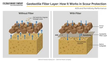
Here is where many scour protection systems fail — not at the armor layer, but beneath it.
Every hard armor system — riprap, gabions, or concrete units — requires a properly designed filter layer to function. Without one, water passing through the armor pulls fine soil particles from the native subgrade upward through the armor voids.
HEC-23 calls this winnowing failure, and it's a primary pier riprap failure mode. The armor stones settle, coverage gaps form, and the scour process accelerates exactly where protection was supposed to stop it.
What Geotextile Filters Do
FHWA HEC-11 defines the filter's role : prevent migration of fine soil particles through armor voids, distribute armor weight across the subgrade, and relieve hydrostatic pressure. Geotextile fabrics serve this function by allowing water to pass through freely while retaining soil particles.
The critical selection parameters are:
- Apparent Opening Size (AOS): Tested per ASTM D4751, AOS reflects the largest opening available for soil passage. Match it to the native soil gradation to retain particles without blinding the fabric.
- Permittivity: Governs how freely water moves through the fabric. Sufficient permittivity prevents hydrostatic pressure buildup beneath the armor layer.
NCHRP Report 568 reinforces this point: because most riprap failure results from scour or undermining at the toe, both the filter and riprap must extend below the anticipated scour depth.
Geotextiles for Iowa Scour Protection Projects
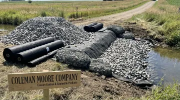
Coleman Moore Company supplies geotextiles — including Mirafi nonwoven and woven fabrics — for scour protection applications on Iowa civil infrastructure projects. The nonwoven options are built for filtration and separation, with polypropylene construction that holds up to UV exposure and the soil chemical environments typical of Iowa field conditions.
For projects requiring more than a filter layer, Coleman Moore also supplies:
- Flexamat — articulated concrete block mats rated for channel velocities of 30+ fps
- ScourStop — a vegetated riprap alternative for culvert outlets, stream banks, and channel protection
Engineers and contractors working on stream crossings, bridge repairs, or channel stabilization can contact Coleman Moore for product guidance and specifications matched to site conditions.
Scour Risk Assessment and Monitoring
Assessment Framework
Before selecting any protection method, engineers must evaluate site-specific risk. HEC-18 provides the U.S. framework for bridge scour evaluation. Key factors to assess:
- Stream hydraulics: design flow velocity and flood return frequency
- Channel geometry: cross-section, alignment, and contraction ratio
- Foundation depth and embedment relative to anticipated scour depths
- Soil erodibility of the native streambed and banks
- Age and condition of any existing protection
Monitoring Technologies
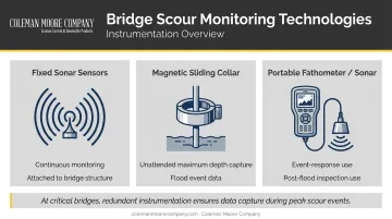
Fixed and portable monitoring tools serve different purposes:
| Tool | Best Use |
|---|---|
| Fixed sonar sensors | Continuous bed elevation record at high-risk piers; attached to bridge structure |
| Magnetic sliding collar | Unattended maximum scour depth measurement during flood events |
| Portable fathometers / sonar | Event-response inspections and post-flood assessments |
Sensors can be damaged or displaced during the same flood events when scour is most active. At critical bridges, redundant instrumentation is the only reliable way to capture data precisely when you need it.
Inspection Requirements
Under 23 CFR Part 650 Subpart C (National Bridge Inspection Standards), bridges must be inspected at intervals not exceeding 24 months. For scour-critical bridges, FHWA requires Plans of Action — documented protocols covering high-flow monitoring and emergency inspection triggers.
Field inspections after significant floods require more than visual checks:
- Scour holes can partially refill with loose sediment between events, masking true depth from above-water observation
- Probing and portable sonar are needed to confirm actual bed conditions at pier foundations
- Above-water visual inspection alone is not sufficient to assess post-flood scour depth
How to Choose the Right Scour Protection Solution
Effective scour protection is a system, not a single material. Undersizing any one component can cause the entire system to fail.
Key Decision Factors
- Site hydraulics: design velocity and bed shear stress at the structure
- Structure type: pier vs. abutment vs. culvert outlet vs. streambank each have different protection geometries and sizing methods
- Available materials and installation constraints: water depth, access, construction season, and equipment
- Regulatory requirements: Iowa DOT standard specifications and FHWA HEC-23 guidance
The Three-Layer System
Every properly designed scour protection system includes:
- Geotextile or granular filter layer: matched to native soil gradation to prevent winnowing
- Armor layer: sized for design flow velocity using HEC-23 equations (riprap, ACB, concrete armor units)
- Edge embedment: the armor perimeter must extend below anticipated scour depth to prevent undermining at the protection boundary
Skipping the filter layer to cut material costs is a short-sighted trade-off. Without it, the armor layer has no long-term stability — subgrade migration causes settlement and displacement, typically during the next high-flow event.
Iowa-Specific Considerations
Iowa's spring snowmelt season and convective storm events create short-duration, high-velocity flows at stream crossings that stress protection systems in ways gradual baseflow conditions don't. For Iowa projects, specifying protection to Iowa DOT revetment classes — rather than generic stone sizes — ensures the armor is calibrated to local design standards.
If you need help matching geotextile filter specifications to site soil conditions for an Iowa project, Coleman Moore Company can assist. Based in Des Moines and serving Iowa civil infrastructure projects since 2004, their team works with contractors and engineers to select products that meet both site requirements and DOT specifications.
Reach them at 515-309-5577 or info@colemanmoorecompany.com.
Frequently Asked Questions
What is scour protection?
Scour protection refers to engineered measures that prevent or minimize erosion of sediment around structure foundations caused by flowing water. Common methods include riprap, geotextile filter layers, gabions, articulated concrete mattresses, and concrete collars. Most effective systems combine a geotextile underlayer with a hard armor surface.
What is scour in construction?
In construction, scour is the erosion and removal of soil or sediment from around a structure's foundation due to water flow. It's a critical concern for bridges, culverts, and stream crossings during both design and construction phases. Temporary works are especially vulnerable before permanent protection is in place.
What are the main types of scour?
The three primary types are local scour, contraction scour, and general long-term degradation. All three can occur simultaneously at a bridge crossing, and total design scour is the sum of all three components.
What materials are commonly used for scour protection?
Nearly all effective scour protection systems include a geotextile or granular filter layer beneath the armor to prevent soil particle migration and winnowing failure. The armor layer itself varies by application — riprap is most common, while gabions, articulated concrete mattresses, and concrete collars suit more demanding hydraulic conditions.
How is scour monitored at bridges?
Primary monitoring tools include fixed sonar sensors, magnetic sliding collar devices, and portable fathometers. Post-flood visual inspections and NBIS-required routine bridge inspections (at intervals not exceeding 24 months) round out a complete monitoring program.
What is the difference between local scour and contraction scour?
Local scour is concentrated erosion around a single pier or abutment, driven by horseshoe and wake vortex formation. Contraction scour affects the entire channel cross-section when flow is forced through a narrower opening, increasing bed shear stress uniformly across the full channel width rather than at isolated structure elements.