Introduction
Civil infrastructure projects routinely hit the same wall: limited right-of-way, soft subgrade conditions, and retaining structure budgets that don't stretch far enough for conventional concrete. Solving all three at once is where mechanically stabilized earth (MSE) earns its place in nearly every DOT and contractor's toolkit.
MSE is soil reinforced with horizontal layers of geosynthetics or steel, creating a composite, load-bearing mass that behaves far more like a solid structure than a pile of dirt. Compared to cast-in-place concrete alternatives, the result installs faster, costs less, and tolerates differential settlement without cracking.
This guide covers what you need to know to work with MSE effectively: how the reinforcement mechanism actually works, the three core components, reinforcement material options, primary applications, key design checks, and where MSE outperforms conventional walls — and where it doesn't.
Key Takeaways
- MSE walls typically cost 30%–50% less than cast-in-place concrete retaining walls of comparable height
- Every MSE system has three elements: a facing, reinforcement layers, and engineered granular backfill
- Applications include highway ramps, bridge abutments, railroad embankments, and landfill expansion
- Minimum reinforcement length is 0.7H (70% of wall height) per FHWA guidance; vertical spacing cannot exceed 32 inches
- Backfill chemistry (pH, resistivity, chlorides, sulfates) is as critical as reinforcement selection for long-term durability
What Is Mechanically Stabilized Earth and How Does It Work?
The Basic Problem MSE Solves
Granular soil can't stand vertically on its own. Its weight generates shear stress along angled failure planes that exceeds the soil's internal friction — the same physics that creates the natural angle of repose in any sand pile. Without intervention, a vertical cut face will always collapse toward that stable angle.
Horizontal reinforcement layers solve this directly. As FHWA describes it, stress transfers continuously between soil and reinforcement through interface friction and passive resistance, binding the material into a composite mass with far greater resistance than either component alone. The relationship works like rebar in concrete: the soil carries compression while the reinforcement resists tension — neither performs the structural work independently.
How the Composite System Forms
The construction sequence builds the composite from the ground up:
- Place and compact a horizontal lift of granular backfill
- Lay reinforcement (geogrid, geotextile, or steel) flat across the lift
- Install facing at the wall face to prevent edge raveling
- Repeat until the design height is reached
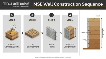
Each lift is structurally stable as placed. No formwork, no curing time, and no cranes for most components. That's why MSE consistently builds faster and at lower cost than poured concrete alternatives.
A Brief History
Modern MSE was formalized by French engineer Henri Vidal in the early 1960s using steel strip reinforcement. The first U.S. highway application came in 1972 on California State Highway 39. Geosynthetic reinforcement followed in the 1970s — the U.S. Forest Service was already deploying geosynthetic-reinforced soil (GRS) systems for mountain roads by the end of that decade.
One terminology note: in the U.S., "mechanically stabilized earth" (MSE) is the generic engineering term. "Reinforced Earth" refers specifically to the proprietary system associated with the Reinforced Earth Company. Outside the U.S., "reinforced soil" is the more common term.
The Three Key Components of an MSE System
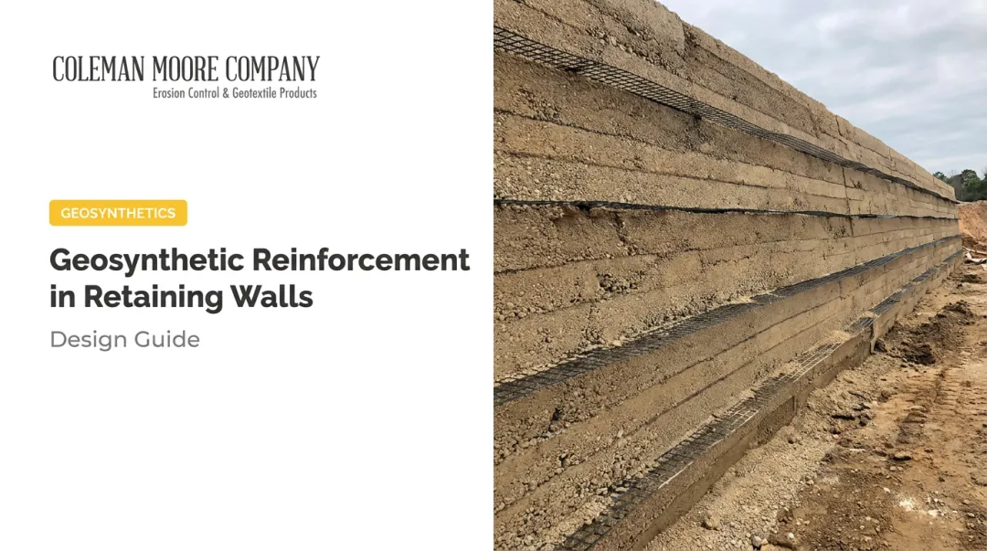
Facing
The facing is the vertical or near-vertical front element of the wall. Common options include:
- Precast concrete panels — interlocking segmental panels, standard in DOT and highway applications; provide a finished appearance and direct connection to reinforcement layers
- Modular concrete blocks — widely used in commercial and site development applications; easier to handle without specialized equipment
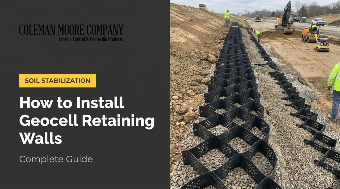
- Wire basket systems or geocells — allow vegetation establishment; preferred where environmental integration or stormwater benefits matter
The facing's primary structural job is preventing edge raveling and connecting to the reinforcement. The reinforced soil mass carries the structural load; the facing holds the edge and anchors the reinforcement grid.
Reinforcement
Reinforcement layers extend horizontally from the facing back into the backfill, tying the facing and fill together into a unified mass. Key FHWA design parameters:
- Minimum length: 0.7H (70% of wall height), with longer embedment often required near the base or under surcharge loading
- Maximum vertical spacing: 32 inches (800 mm)
Friction and mechanical interlock between reinforcement and backfill binds the entire mass into a unified structure. This interface — not the reinforcement material alone — is where the system's strength comes from.
Backfill
Granular, free-draining soils (clean sands and gravels) are required. Three performance requirements drive this:
- High friction angles maximize soil-reinforcement interaction
- Free drainage prevents pore water pressure buildup
- Controlled chemistry protects reinforcement from corrosion or degradation
Avoid cohesive or clayey soils entirely — even when they appear cost-competitive with granular material. The drainage and friction angle penalties compound over time and are not recoverable once the wall is built.
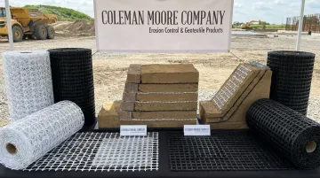
Reinforcement Materials for MSE Structures
Three reinforcement categories are in common use: steel strips/mats, woven geotextiles, and geogrids.
Steel Reinforcement
Galvanized steel strips and welded wire mats remain standard in many DOT highway wall applications. Achieving a 75–100 year service life means treating galvanizing and backfill chemistry as a single integrated system:
| Parameter | FHWA Requirement |
|---|---|
| Coating standard | AASHTO M 111 / ASTM A123 |
| Coating thickness | 2.0 oz/ft² (85 micrometers) |
| Backfill pH | 5–10 |
| Backfill resistivity | > 3,000 ohm-cm |
| Chloride content | < 100 ppm |
| Sulfate content | < 200 ppm |
Iowa DOT Section 2432 (revised April 2026) is the applicable state specification for Iowa projects — it supplements but doesn't replace the FHWA baseline.
Coleman Moore's reinforcement offering focuses exclusively on geosynthetic products. For projects requiring steel strip or welded wire mat reinforcement, coordinate directly with steel fabricators who can meet these galvanizing specifications.
Geotextile Reinforcement
Woven geotextiles provide tensile reinforcement through soil friction across their surfaces. Advantages include flexibility, light weight, and corrosion resistance — making them well-suited for wrapped-face walls and lower-to-mid height structures.
Two limitations to design around:
- Creep under sustained tensile load can reduce effective long-term strength below short-term test values
- UV degradation occurs before burial; geotextiles must be covered promptly during construction
Where woven geotextile reinforcement fits the design, Coleman Moore supplies products from Mirafi and Huesker for soil reinforcement applications across Iowa infrastructure projects.
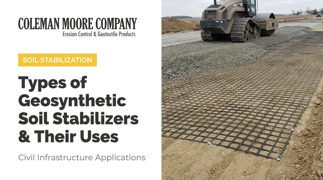
Geogrid Reinforcement
Geogrids — open-grid polymer structures made from HDPE, polyester, or polypropylene — develop pullout resistance through two mechanisms: surface friction and mechanical interlock, where soil particles engage within the grid apertures. That passive resistance from the transverse ribs gives geogrids high pullout resistance relative to their weight.
Long-term design strength requires reduction factors for:
- Creep under sustained load
- Installation damage during construction
- Chemical and biological degradation over the design life
GRI GG4b provides the standard framework for calculating allowable design strengths from short-term test values. Omitting these reductions produces unconservative designs and should never be treated as optional.
Coleman Moore supplies geogrids from Tensar (including the Tensar InterAx® Geogrid) and Huesker (Fortrac® geogrids) for MSE wall and reinforced slope applications throughout Iowa.
The Huesker Fortrac® line is specifically designed for GRS walls and slopes, offering high tensile strength with low strain and solid resistance to soil chemicals, UV, and mechanical damage. Coleman Moore provides product selection support — matching geogrid strength and configuration to wall height, loading, and backfill chemistry — for engineers and contractors working through design decisions.
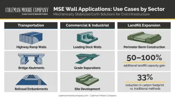
Common MSE Applications Across Civil Infrastructure
Transportation
Transportation accounts for the bulk of MSE wall construction. NCHRP research reports that millions of square feet of MSE retaining wall are constructed annually in the United States. Common applications include:
- Highway retaining walls at interchange ramps and roadway widening projects
- Bridge abutments (designed to a 100-year service life for critical applications)
- Overpass approach walls
- Railroad embankment support in space-constrained corridors
DOTs consistently specify MSE for these applications because it performs well at scale, installs without cranes or formwork, and is well-covered by established design standards (FHWA-NHI-10-024).
Commercial and Industrial Site Development
MSE walls handle grade separations, loading dock support walls, and parking structure support in commercial development — anywhere a vertical or near-vertical retained earth face is needed without the footprint or cost of a concrete structure.
That flexibility extends to heavy industrial sites as well. At CF Industries' plant expansion in Sergeant Bluff, Iowa, Coleman Moore's geosynthetic design approach — starting from on-site DCP testing — reduced aggregate requirements on a site where measured CBR came in at just 1.0%, demonstrating how subgrade data at the design stage directly shapes material efficiency.
Landfill Expansion
MSE berms are a particularly efficient tool for landfill expansion. Geosynthetics Magazine reports that MSE berms can increase landfill capacity by 50%–100% by enabling vertical rather than horizontal expansion. The same source documents that a 0.5H:1V MSE berm carries a 33% lower carbon footprint than a traditional 3H:1V unreinforced berm — a meaningful sustainability differentiator on public projects with environmental reporting requirements.
Key MSE Design Considerations
Global Stability First
Before sizing reinforcement, confirm that potential failure surfaces — including those that pass through the reinforced zone and extend into foundation or retained soil — have adequate factors of safety. This step sets the wall height, berm width, and rough reinforced zone geometry. It's the starting point, not an afterthought.
The governing federal reference is FHWA-NHI-10-024 (FHWA GEC 011, November 2009). All subsequent design steps should trace back to it.
Internal Reinforcement Design
Key parameters:
- Vertical spacing: Not to exceed 32 inches per FHWA; typically 2–3 feet in practice
- Reinforcement length: Minimum 0.7H; longer near the base or under surcharge
- Tensile strength: Increases with depth — most designs use two or three different reinforcement strength tiers rather than uniform strength throughout the wall height
External Stability Checks
Three external checks are required per FHWA guidelines:
- Sliding — horizontal movement of the reinforced mass
- Bearing capacity — foundation soil supporting the total wall load
- Eccentricity — rotational overturning resistance
These rarely govern over global stability for typical MSE walls, but must be verified regardless.
Drainage and Backfill Quality
Saturated backfill builds pore water pressure that directly degrades stability. It's one of the most common sources of long-term MSE performance problems. Free-draining granular backfill and properly detailed drainage are non-negotiable, even when clayey soils look cheaper at the bid stage.
Site Assessment Tools
Accurate subgrade data is critical before finalizing MSE wall geometry and reinforcement layout. Coleman Moore's on-site DCP (Dynamic Cone Penetrometer) testing delivers rapid subgrade strength data, converting penetration readings to CBR values that feed directly into Tensar Plus design software.
The software's design modules — covering subgrade stabilization, unpaved roads, heavy haul roads, and asphalt pavement — generate optimized aggregate thickness recommendations that reduce material quantities and construction costs. Iowa engineers and contractors can access this field-to-software workflow through Coleman Moore at any project stage.
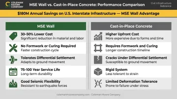
MSE vs. Traditional Retaining Walls: Cost and Performance
Cost
The TRB/FHWA cost comparison puts MSE wall construction at 30%–50% less than cast-in-place concrete walls of comparable height, with FHWA estimating annual Interstate construction savings of approximately $180 million. Savings come from:
- No formwork or curing
- Lightweight components that don't require cranes
- Fewer specialized trades
- Faster construction schedule
These are planning-level figures. Actual bids vary based on wall height, facing type, backfill availability, right-of-way, drainage complexity, and foundation conditions.
Cost is only part of the picture. MSE walls also outperform rigid concrete alternatives in several critical performance categories.
Performance Advantages
- Differential settlement: MSE walls tolerate movement that would crack a rigid concrete wall. Iowa DOT's specification requires wall panels to accommodate 1 ft of differential settlement per 100 ft of wall length — a concrete performance standard that validates the system's flexibility.
- Seismic performance: Caltrans documented good MSE wall response in the 1989 Loma Prieta and 1994 Northridge earthquakes. The flexible, reinforced-soil system retains structural integrity through large deformations better than rigid alternatives, though performance still depends on design quality and site conditions.
- Service life: 75 years minimum for permanent walls; 100 years for bridge abutments and critical structures per FHWA, when backfill chemistry and drainage specifications are met.
When MSE Is Not the Right Choice
MSE has real constraints that should screen it out early on some projects:
- Insufficient right-of-way: Reinforcement extending 0.7H back into the retained fill requires physical space. MoDOT notes a minimum of 8 feet or 70% of wall height. Without that footprint, MSE isn't viable.
- Aggressive soil chemistry: Low pH, high chlorides, acid mine drainage, or industrial contamination can compromise both galvanized steel and geosynthetic reinforcement.
- Scour exposure: Floodplain conditions that could undermine the reinforced zone are a significant risk.
- Future utility conflicts: Cutting reinforcement layers for future utility access compromises the wall's structural integrity.
- Near-zero deformation requirements: MSE is a flexible system. Projects with extremely tight deformation tolerances need careful geotechnical evaluation before MSE is specified.
Catching these constraints at the site screening stage avoids costly redesigns — and keeps the project on the right structural system from the start.
Frequently Asked Questions
What is mechanically stabilized earth used for?
MSE is used for retaining walls, bridge abutments, highway ramps and overpasses, railroad embankments, commercial grade separations, loading dock walls, landfill expansion berms, seawalls, and dikes — any application requiring a stable, load-bearing earth structure with a vertical or near-vertical face.
What is the typical lifespan of an MSE wall?
FHWA specifies a minimum 75-year service life for permanent MSE walls, and 100 years for bridge abutments and critical structures. Both require controlled backfill chemistry (pH, resistivity, chloride, sulfate), adequate drainage design, and reinforcement selected for the specific service environment.
What are the three main components of an MSE structure?
Facing (the front wall element), reinforcement (geogrids, geotextiles, or steel strips extending horizontally into the backfill), and engineered granular backfill. The structural strength comes from friction and mechanical interlock between the reinforcement and backfill — not from the facing alone.
What type of reinforcement is best for MSE walls?
Geogrids are widely specified, especially in modular block MSE systems, due to high pullout resistance, corrosion resistance, and ease of installation. Steel strips and welded wire mats remain common in DOT highway walls where galvanizing specifications can be closely controlled — the right choice depends on wall height, loading, backfill chemistry, and design life.
What soils can be used as MSE backfill?
Clean granular soils — sands and gravels — are required. Backfill specifications control pH (5–10), resistivity (>3,000 ohm-cm), chloride (<100 ppm), and sulfate content (<200 ppm). Cohesive or clayey soils are not acceptable — drainage limitations and reduced friction angles make them unsuitable regardless of cost.
How does MSE compare in cost to a concrete retaining wall?
MSE walls typically cost 30%–50% less than cast-in-place concrete alternatives. Savings come from faster construction, no formwork or curing, lighter components, and lower labor requirements. The exact differential depends on wall height, facing type, and site conditions.