The consequences of getting it wrong go beyond rework costs. Wall failures involving reinforced soil masses can result in property damage, road closures, and safety hazards that are expensive and disruptive to remediate after the fact.
This guide is a practical reference for civil and geotechnical engineers, contractors, and project managers working on geosynthetic-reinforced retaining wall projects. It covers when reinforcement is needed, how to establish design parameters, what a correct installation sequence looks like, and how to catch and correct the problems that appear most often in the field.
Key Takeaways
- Walls exceeding 3–4 ft commonly warrant engineering review for geosynthetic reinforcement, particularly with surcharge loads or constrained sites
- Geogrids and high-strength geotextiles are the two primary reinforcement materials — each suits different soil and drainage conditions
- Reinforcement layer spacing, embedment length, and connection strength must be engineer-specified for each project
- Select granular backfill compacted to 95–100% of AASHTO T 99 is a non-negotiable performance requirement
- Post-installation validation (compaction records, layer alignment, drainage checks) is a required hold point before proceeding
When Does a Retaining Wall Need Geosynthetic Reinforcement?
Not every retaining wall requires geosynthetic reinforcement. Gravity walls — relying on their own mass to resist lateral earth pressure — work well at modest heights with favorable soil and loading conditions. The question is where that stops being enough.
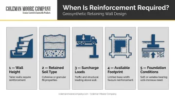
Industry guidance from Tensar identifies walls taller than 3–4 ft as commonly warranting evaluation for geogrid reinforcement. That threshold is a screening trigger, not a hard design rule — the actual determination depends on several interacting factors:
- Wall height — taller walls generate more lateral pressure on the facing
- Retained soil type — cohesive or poorly graded soils increase lateral load and drainage risk
- Surcharge loads — traffic, structures, or stockpiles behind the wall add significant pressure
- Available footprint — a conventional gravity wall or slope requires more horizontal space than a reinforced soil mass
- Foundation conditions — weak native soils reduce bearing capacity and complicate external stability
When multiple factors stack up, the structural logic of the wall itself needs to change.
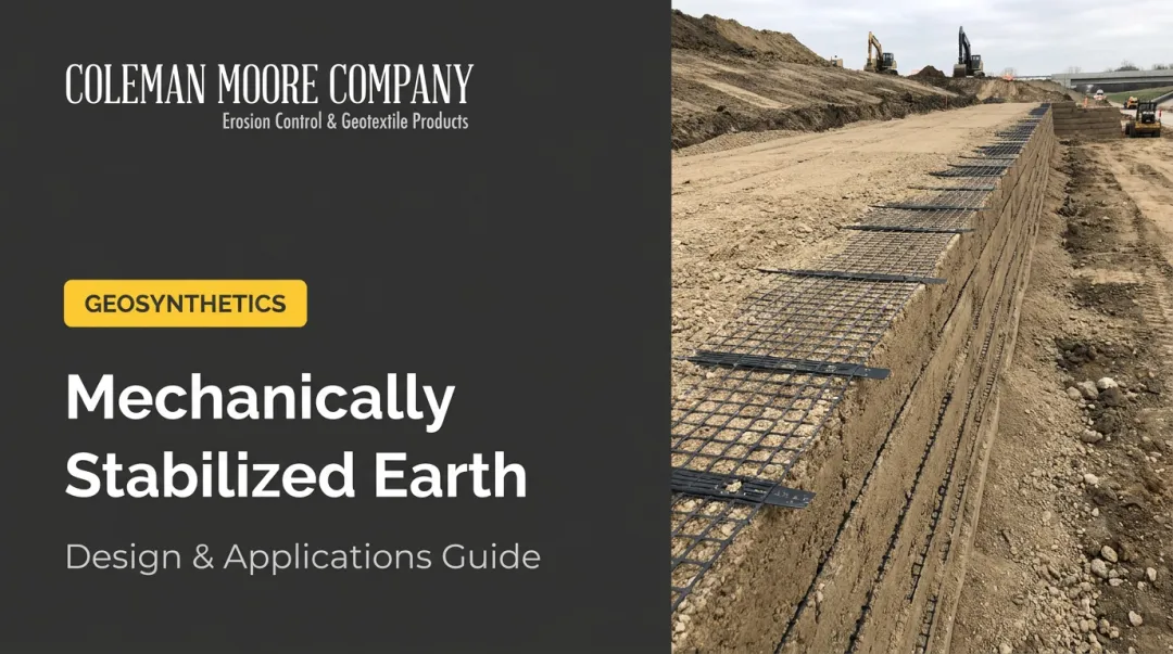
What Reinforcement Actually Does
Geosynthetic reinforcement transforms the wall from a facing that resists pressure into a composite reinforced soil mass. The geosynthetic layers tie back into the retained fill, creating a large rectangular block of stabilized earth that distributes load over a much wider zone. According to FHWA, MSE (mechanically stabilized earth) walls are technically feasible above 100 ft, with the tallest permanent U.S. example reaching approximately 135 ft of exposed height — a scale that simply isn't achievable by massing alone.
Reinforcement becomes the practical answer on steep or constrained sites, wherever road or structural loads bear on the retained soil, and on projects where weak native soils rule out a conventional wall footing. In each case, the goal is the same: build a stable mass rather than resist pressure with a single facing element.
Design Parameters and Prerequisites
Before any reinforcement layout can be developed, a defined set of design inputs must be established. Skipping this step leads to under-designed walls or over-specified materials — both costly in different ways.
Core Design Inputs
| Parameter | Purpose |
|---|---|
| Wall height (H) | Sets geometry for reinforcement length and layer count |
| Retained soil friction angle, cohesion, unit weight | Drives lateral earth pressure calculations |
| Foundation soil bearing capacity | Required for external stability checks |
| Surcharge loads | Traffic, structural, or equipment loads behind the wall |
| Seismic considerations | Required in applicable zones per AASHTO LRFD |
Reduction Factors and Long-Term Design Strength
The allowable long-term tensile strength of a geosynthetic is not its catalog ultimate strength. FHWA's design framework defines it as:
T_al = T_ult ÷ (RF_ID × RF_CR × RF_D)
Where:
- RF_ID = installation damage reduction factor (minimum 1.1 per FHWA)
- RF_CR = creep reduction factor under sustained tensile load
- RF_D = durability factor for chemical/biological degradation
When product-specific data isn't available, FHWA identifies a preliminary total reduction factor of 7 as appropriate for permanent structures. Backfill quality directly affects RF_ID: abrasive or oversized particles increase installation damage risk, which is one reason gradation controls matter from a structural standpoint, not just for drainage.
Failure Modes to Check
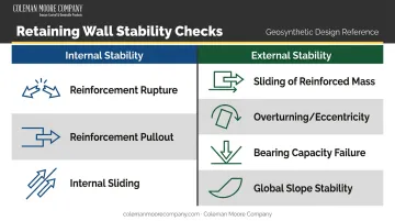
A complete design addresses two stability categories — internal and external — and must check both simultaneously:
Internal stability:
- Reinforcement rupture (tensile breakage)
- Reinforcement pullout from the soil mass
- Internal sliding between reinforcement layers
External stability:
- Sliding of the entire reinforced mass
- Overturning / limiting eccentricity
- Bearing capacity failure at the foundation
- Global slope stability
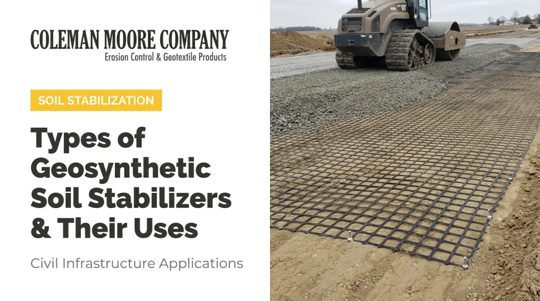
Geosynthetic Selection and Layout
Geogrids develop pullout resistance through a combination of friction and passive bearing against soil particles interlocked in their apertures. High-strength geotextiles develop resistance through friction alone but can also perform filtration and separation functions.
For GRS walls and slopes requiring high tensile strength with low strain, Huesker Fortrac® geogrids are a well-matched product class — Coleman Moore carries Fortrac® and other Huesker geosynthetics suited to retaining wall applications.
Key layout parameters per FHWA guidance:
- Minimum reinforcement length: Greater of 0.7H or 8 ft
- Maximum vertical spacing: 32 in. to maintain a coherent reinforced zone
- Connection strength at the wall face must be verified per ASTM D6638 for segmental block systems
How to Design and Install a Geosynthetic-Reinforced Retaining Wall
Design and installation follow a defined sequence. Each layer of compacted fill and each geosynthetic layer depends on the one below it. Shortcutting any step compromises the whole structure.
Step 1: Prepare the Site and Foundation
Excavate to a level bearing stratum and remove all unsuitable material — organic matter, soft spots, vegetation, and any slide debris. FHWA identifies poor foundation preparation as a leading driver of external stability failures.
Before wall construction begins, verify that actual foundation conditions match the bearing capacity assumed in the design. If soft or unexpected soils are encountered, stop and reassess. Installing a reinforced wall on an inadequate foundation makes the reinforcement irrelevant.
Step 2: Select and Lay Out Geosynthetic Reinforcement
Follow the engineer's reinforcement schedule exactly. This document specifies geosynthetic grade, layer spacing, and embedment length for every course in the wall. Deviating from it — even slightly — undermines the pullout resistance and load distribution the design depends on.
Installation procedure:
- Unroll geosynthetic perpendicular to the wall face
- Position flat — no folds, wrinkles, or overlapping
- Extend to the full design embedment length specified in the drawings
- For geogrids, ensure the principal strength direction runs perpendicular to the wall face
Step 3: Place and Compact Backfill
Select granular backfill must meet FHWA gradation requirements:
| Sieve | Requirement |
|---|---|
| 4-inch sieve | 100% passing |
| No. 40 sieve | 0–60% passing |
| No. 200 sieve | 0–15% passing |
| Plasticity Index | PI < 6 |
Place fill in loose lifts not exceeding 12 inches and compact to 95–100% of AASHTO T 99 maximum dry density before placing the next geosynthetic layer. Do not operate heavy compaction equipment directly on unprotected geosynthetics. Keep equipment at least 3 ft from the wall face; use hand-operated compactors within that zone.
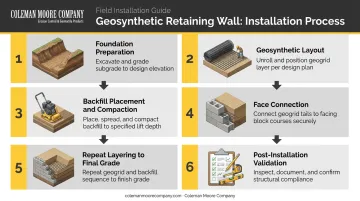
Step 4: Connect Reinforcement to Wall Face
The geosynthetic layer must connect to the facing unit — segmental block, concrete panel, or wrapped face — with sufficient strength to resist lateral earth pressure under service conditions. Different facing systems use different connection mechanisms; connection strength must be verified against design requirements, not assumed.
ASTM D6638 governs connection testing between geosynthetic reinforcement and segmental concrete block units.
Step 5: Continue Layering and Final Grading
With connections verified at each course, repeat the fill-compact-reinforce sequence up the full wall height. Once construction reaches final grade:
- Grade the retained area to match design grades
- Direct surface drainage away from the wall
- Confirm drainage outlets are unobstructed and functional
Step 6: Post-Installation Validation
Validation is a hold point, not a formality. Check:
- Confirm each geosynthetic layer sits at the correct elevation per design drawings
- Verify as-built embedment length against design requirements before fill covers each layer
- Document density test results for every compacted lift
- Inspect facing connections for gaps, tears, or misalignment
- Check the wall face is plumb within tolerance, with no bulging or bowing
A wall face that bulges or shows visible movement shortly after construction almost always traces back to a step in this sequence that was skipped or inadequately executed.
Common Design and Installation Problems
These three problems account for the majority of geosynthetic wall failures observed in the field. Each is preventable — most come down to specification enforcement during construction, not design error.
Insufficient Reinforcement Embedment Length
What it looks like: The wall face bulges outward, or the reinforced soil mass appears to pull away from the facing, especially under surcharge.
Likely cause: Embedment length was specified shorter than required by design calculations, or the backfill zone behind the face was narrower than designed — meaning reinforcement wasn't anchored far enough behind the theoretical failure plane.
Fix: Verify as-built embedment against design drawings at each layer during construction, before fill is placed. If the wall is already built and embedment is insufficient, a forensic review is needed. Remediation may require soil nail or anchor supplementation, which is more expensive than getting it right the first time.
Poor Backfill Quality or Compaction
Signs: Progressive wall face movement, settlement in the retained area, or reinforcement pullout under load — often appearing months after construction when traffic or surcharge loads are applied.
Root cause: Cohesive, fine-grained, or improperly compacted fill in the reinforced zone. This reduces soil-geosynthetic friction, elevates creep potential in the reinforcement, and can trap water behind the facing.
Fix: Enforce backfill material specifications and compaction testing at every lift. FHWA minimum acceptance criteria for reinforced backfill are non-negotiable:
- PI < 6
- Maximum 15% passing the No. 200 sieve
- 95–100% compaction per AASHTO T 99
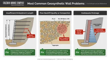
Inadequate Drainage Behind the Wall
What it looks like: Hydrostatic pressure buildup behind the facing, lateral wall movement, or piping of fine material through the face joints.
Likely cause: Missing or blocked drainage aggregate layer, absent geotextile filter where fine soils are present, or no adequate outlet at the base of the wall. FHWA specifically requires subsurface drainage features — collector systems with weepholes — as standard practice for MSE walls.
Fix: Incorporate a granular drainage aggregate zone directly behind the facing, with a geotextile filter layer separating it from the retained soil. Coleman Moore stocks Mirafi and Huesker nonwoven geotextiles suited for this filtration application. Include drainage outlets at the wall base and inspect them as part of post-installation validation.
Pro Tips for Geosynthetic-Reinforced Retaining Wall Projects
From design to final lift, a few disciplined habits separate retaining walls that perform for decades from ones that develop problems within a few years. Here are three field-tested practices worth building into every project.
Use Design Software to Optimize Reinforcement Layout
Tools like Tensar Plus allow engineers to input site-specific soil parameters and load conditions to dial in geosynthetic grades and layer spacing. The output often reveals opportunities to reduce material without sacrificing performance. Coleman Moore incorporates this kind of software-based analysis into project consultation, helping contractors and engineers make informed material selections before the first course is set.
Sequence Compaction Equipment Carefully
Keep heavy compaction equipment at least 3 ft from the wall face at all times. Use hand-operated plate compactors within that zone. Overstressing facing units with heavy equipment causes damage that isn't always visible immediately — but it will affect long-term wall performance.
Document Every Layer Before It's Buried
Photograph each geosynthetic layer before fill placement, record density test results by lift, and tie all documentation to the design drawing layer number. This record protects the engineer, the contractor, and the owner. It also provides a clear baseline if performance questions arise years later.
Frequently Asked Questions
Does a 4 ft retaining wall need geosynthetic reinforcement?
Walls at or below 4 ft can often be designed as gravity walls under favorable conditions. However, significant surcharge loads, poor native soils, or a limited base width can push a borderline wall into reinforcement territory quickly. Any wall at this height with those complicating factors should be formally evaluated by an engineer before assuming gravity design is sufficient.
How long does geosynthetic reinforcement typically last?
FHWA's current MSE wall design guidance specifies a minimum 75-year service life for permanent retaining walls and 100 years for critical structures supporting bridge abutments or buildings. Achieving that service life depends on meeting environmental compatibility criteria: reinforced fill resistivity, pH range, and reduction factor documentation. Material type alone doesn't determine durability.
Which property of geosynthetic reinforcement is most critical for its effectiveness?
Tensile stiffness (resistance to elongation under working stress) is the property that controls how effectively reinforcement restrains soil movement during service. Ultimate tensile strength is a separate value used specifically for rupture limit-state checks, after reduction factors are applied.
What is the difference between geogrids and geotextiles in retaining wall reinforcement?
Geogrids develop pullout resistance through soil interlock across their open apertures, making them the primary choice for MSE wall reinforcement. High-strength geotextiles rely on friction alone for pullout resistance but can also provide filtration and separation functions where drainage management is a concurrent requirement.
How do I determine the correct geosynthetic layer spacing and embedment length?
Spacing and embedment length are outputs of formal design calculations covering pullout, rupture, sliding, and bearing, using site-specific soil parameters, wall height, and surcharge loads. A qualified engineer must specify these values. Generic tables from product literature serve as a budgeting reference only — not a replacement for project-specific design.
What backfill material works best with geosynthetic-reinforced retaining walls?
Well-graded granular fill — clean sand or gravel meeting FHWA's gradation limits (PI < 6, max 15% passing No. 200) — is strongly preferred. FHWA identifies 34 degrees as the default friction angle for qualifying select backfill. Cohesive or fine-grained soils reduce soil-geosynthetic friction and complicate drainage, both of which degrade long-term wall performance.