Introduction
Embankments built over soft or weak soils are a persistent headache in civil infrastructure. Without proper reinforcement, they're vulnerable to slope failure, bearing capacity collapse, and differential settlement — failures that halt construction and cost significantly more to remediate than to prevent through good design.
According to the FHWA, up to 50% of major infrastructure projects experience significant schedule or cost impacts from geotechnical issues. For embankment-heavy work — highway widening, access road construction, municipal fills over low-lying ground — that exposure is very real.
Geogrid reinforcement has become the standard engineering response. Specifying and analyzing a geogrid-reinforced embankment, however, demands more than product selection. It requires a clear understanding of soil conditions, geogrid properties, failure modes, and design methodology — otherwise the solution underperforms and the problems return.
This guide walks through how geogrid embankment reinforcement works, the step-by-step design and analysis process, and a practical project walkthrough. Whether you're an engineer selecting reinforcement for a highway fill, a contractor interpreting the drawings, or a project owner evaluating soft ground options, you'll find the technical grounding and practical context to move forward with confidence.
Key Takeaways
- Geogrid reinforcement resists slope failure, bearing capacity failure, and settlement in embankments over weak soils
- All three failure modes — internal, external, and global/compound stability — must be checked independently in design
- Long-term design strength — not ultimate tensile strength — governs geogrid selection
- Foundation soil CBR below 3–3.5% is a common trigger condition for basal reinforcement
- Site investigation and limit equilibrium analysis confirm which failure modes govern and validate reinforcement layout
What Is Geogrid Embankment Reinforcement?
Geogrid embankment reinforcement places layers of high-tensile-strength polymer grid material within or beneath an embankment fill. The goal is to increase structural stability and resist deformation under load — especially where foundation soils are soft, compressible, or inconsistent.
How Geogrids Work Mechanically
The key is the open aperture structure. As defined by ASTM D4439, a geogrid is a geosynthetic formed by integrally connected elements with apertures greater than ¼ inch, allowing soil or aggregate particles to interlock with the geogrid ribs. That interlocking creates a composite reinforced mass that resists:
- Lateral spreading of fill under load
- Slope failure along critical surfaces
- Differential settlement from variable foundation support
Unlike geotextiles, which primarily separate or filter, geogrids are selected specifically for tensile reinforcement. For embankment applications, uniaxial geogrids dominate because they deliver high tensile strength in the primary load direction (across the slope).
MSE Walls vs. Reinforced Soil Slopes
Two main system types apply to embankment projects:
- Mechanically Stabilized Earth (MSE) walls — use multiple geogrid layers with a structural facing element to create near-vertical or steeply retained fills; designed under LRFD per AASHTO
- Reinforced Soil Slopes (RSS) — use geogrid to steepen slopes beyond what unreinforced soil could sustain; FHWA defines RSS as face inclinations less than 70 degrees; designed using limit equilibrium on an ASD basis
Polymer type directly affects long-term design strength. Creep reduction factors vary considerably across materials per FHWA:
| Polymer | Creep Reduction Factor |
|---|---|
| PET (Polyester) | 1.6–2.5 |
| HDPE | 2.6–5.0 |
| PP (Polypropylene) | 4.0–5.0 |

A lower creep reduction factor means more of the geogrid's tensile strength is available for design over a 75- to 100-year service life.
Why Geogrid Reinforcement Is Critical for Embankments
An unreinforced embankment over weak ground carries real engineering, schedule, and budget consequences. Soft clay, saturated silt, and organic soils can't support the shear stresses from fill placement — and when they fail, failure is often sudden and progressive.
Failure Modes That Drive the Risk
Without reinforcement, embankments over weak soils are exposed to:
- Global sliding — the entire fill mass sliding along a deep failure surface through the foundation
- Bearing capacity failure — the foundation soil punching under the embankment load
- Slope instability — face failures and rotational slips
- Excessive settlement — consolidation of soft foundation soils causing uneven movement
Each of these can trigger project shutdowns, costly remediation, or redesign.
Engineering and Project Benefits
The cost case for reinforcement is well documented. FHWA data shows MSE wall solutions — one geogrid-reinforced system type — typically save **25–50% versus conventional reinforced concrete retaining structures**, with savings exceeding 50% where piles and pile caps are avoided.
Geogrid reinforcement delivers measurable value across multiple dimensions:
- Increases the factor of safety against slope failure, allowing steeper slopes and smaller right-of-way footprint
- Reduces imported fill and granular material quantities, cutting material and haulage costs
- Enables construction over soft ground that would otherwise require deep improvement or piled foundations
- Extends service life by limiting long-term differential settlement
- Cuts construction timelines compared to alternatives like surcharging with wick drains, which can add months to a schedule
The right approach depends on foundation soil strength (CBR or undrained shear strength), embankment height and geometry, surcharge loading, and required design life. None of those inputs can be assumed — each has to be measured and designed for explicitly.
Key Design Inputs and Considerations
Reliable geogrid embankment design starts with site data, not product selection. Skipping thorough characterization is where most problems begin.
Foundation Soil Assessment
Engineers need to establish:
- CBR or undrained shear strength (Su) at multiple locations across the embankment footprint
- Consolidation potential and settlement magnitude
- Groundwater depth and seasonal variation
- Presence of soft layers, organic material, or subsurface variability that could govern the critical failure surface
Dynamic Cone Penetrometer (DCP) testing per ASTM D6951 is one of the most effective field tools for this — the 8-kg hammer penetration rate converts directly to in-situ CBR values and helps identify layer boundaries quickly across large footprints.
Geogrid Material Properties
Geogrids vary considerably, and the numbers that matter for design are calculated from test data, not read off the product label:
- Ultimate tensile strength (UTS) — measured by ASTM D4595 or D6637; the starting point, not the design value
- Long-term design strength (LTDS) — calculated as Tal = Tult / (RFID × RFCR × RFD), accounting for installation damage, creep, and durability reduction factors over the design life (typically 75–100 years for permanent structures)
- Soil-geogrid interaction coefficients — pullout resistance and direct sliding factors that depend on both geogrid type and fill gradation; project-specific testing is required for non-standard materials
Failure Modes to Check
Every geogrid embankment design must verify three failure mode categories:
| Category | What's Being Checked |
|---|---|
| Internal stability | Tensile rupture of geogrid layers; pullout of reinforcement from the soil mass |
| External stability | Sliding along the base of the reinforced zone; bearing capacity of the foundation |
| Global/compound stability | Deep-seated failure surfaces passing through or around the reinforced zone |
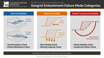
All three must achieve adequate factors of safety (or resistance factors under LRFD).
Design Methodology and Fill Requirements
The verification framework ties directly into the analytical method used. Key standards and tools by structure type:
- MSE walls: LRFD methodology per AASHTO, designed using MSEW
- RSS slopes: ASD basis using limit equilibrium, analyzed with ReSSA
- Design optimization: Tensar Plus enables geogrid spacing and aggregate thickness refinement for both structure types
Fill gradation requirements differ by structure type:
- MSE walls: Maximum 15% passing No. 200 sieve, PI below 6 — granular select fill is strongly preferred
- RSS: Up to 50% passing No. 200 sieve, PI below 20 — more tolerant of marginal material
- Cohesive or marginal fill: Introduces pore pressure buildup risk and typically requires reduced geogrid spacing and staged construction or drainage provisions
How Geogrid Embankment Design & Analysis Works — Step by Step
Every project is different, but the design sequence is consistent. Skipping any stage — especially site investigation or stability verification — is where most field problems begin.
Step 1 — Site Investigation and Soil Characterization
Conduct field testing across the full embankment footprint:
- Collect CBR or undrained shear strength values at multiple locations
- Identify soft layers, organic deposits, or lateral variability that could control the critical failure surface
- Document groundwater levels for both short-term (undrained) and long-term (drained) stability cases
Step 2 — Define Design Requirements and Geometry
Nail down the governing parameters before selecting materials:
- Establish embankment height, slope ratio (H:V), crest width, design loading, and design life
- Set minimum target factor of safety — FHWA supports FS ≥ 1.3 for MSE/RSS applications
- Confirm whether the structure classifies as an MSE wall or RSS, since each follows a different design standard
Step 3 — Select Geogrid Type and Initial Layout
Match geogrid selection to calculated tensile force demands, then set the initial layout:
- Select a grade with sufficient long-term design strength (LTDS) for the applied loads
- Keep vertical spacing at 32 inches (800 mm) maximum per FHWA to maintain a coherent reinforced mass
- Size primary reinforcement length as the greater of 0.7H or 8 feet for MSE walls
- Add secondary layers near the face where surficial stability is a concern
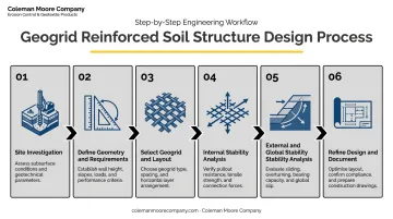
Step 4 — Perform Internal Stability Analysis
Calculate the maximum tensile force in each layer using the Simplified Method or limit equilibrium, then verify:
- LTDS exceeds tensile demand with adequate safety margin
- Pullout capacity at each layer, using soil-geogrid interaction coefficients and effective overburden stress
- Upper layers specifically — low overburden makes pullout the frequent controlling condition here
Step 5 — Perform External and Global Stability Analysis
Run limit equilibrium analysis using software such as ReSSA or Slide. Check for:
- Global, compound, and base sliding failure modes
- Both circular and wedge-type failure surfaces
- The undrained short-term stability case separately — for embankments over soft ground, this typically governs over the long-term drained condition
Step 6 — Refine Design and Prepare Construction Documents
With analysis complete, refine the design and document it for the field:
- Adjust geogrid spacing, length, or grade based on analysis results
- Finalize fill specification and compaction requirements
- Document lift thickness, placement sequence, and facing construction details
- Specify QC testing requirements — include on-site installation damage assessment if fill gradation differs from standard assumptions
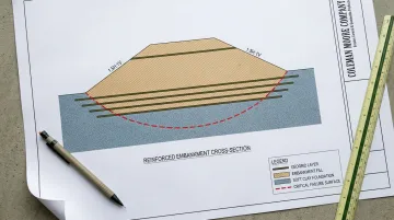
A Practical Walkthrough: Geogrid-Reinforced Embankment Over Soft Ground
Here's how the design process plays out in a real-world scenario.
The situation: A 20-foot-high access road embankment needs to be constructed across a low-lying area with soft, saturated clay foundation soils — CBR approximately 2–3%. Without reinforcement, stability analysis shows the unreinforced embankment fails to meet minimum safety requirements. Conventional alternatives — mass excavation or a wick drain/surcharge program — add weeks and significant cost.
Site investigation and design approach: DCP testing across the site confirms consistently low CBR values with some lateral variability. The design engineer targets a factor of safety of 1.3 for global stability and selects a 1.5H:1V slope geometry. Limit equilibrium analysis shows multiple layers of high-strength uniaxial polyester geogrid are required — spaced at 18-inch vertical intervals in the lower half of the embankment and 24-inch intervals in the upper half.
What the analysis reveals: The critical failure surface passes through the soft clay foundation, confirming this is a compound/global stability problem — not just internal slope reinforcement. The lowest geogrid layer, placed at the embankment base, carries the highest tensile load and governs the design. This is a common finding that engineers must check explicitly rather than assuming uniform load distribution across all layers.
Finalizing the design: After verifying pullout capacity and upgrading the bottom three layers to a higher-strength geogrid grade, all stability checks pass. The reinforced embankment solution:
- Eliminates the need for mass excavation
- Removes the wick drain/surcharge delay from the schedule
- Reduces total construction cost compared to the ground improvement alternative
- Allows the project to proceed on schedule
When the design process is followed correctly, the numbers speak for themselves: avoided remediation, a shorter schedule, and a lower total project cost than any ground improvement alternative on the table.
How Coleman Moore Company Can Help
For contractors, engineers, and project owners in Iowa dealing with soft ground embankment challenges, Coleman Moore Company offers a direct path from soil assessment to design to product supply — backed by over two decades of field experience since 2004. Based in Des Moines, the company has supplied geogrids and geosynthetics to Iowa contractors, engineers, municipalities, and DOTs since 2004 — and their support goes well beyond product delivery.
Site Assessment and Design Integration
Coleman Moore performs on-site DCP testing to quantify subgrade conditions before design work begins. Their team sets up test patterns (grid layouts for large areas, linear profiles along road alignments), converts penetration data into CBR values, and feeds those values into Tensar Plus design software to calculate optimized aggregate thickness and reinforcement specifications.
At the CF Industries Plant Expansion in Sergeant Bluff, Iowa, where foundation CBR measured just 1.0%, this process produced an optimized design that reduced required aggregate thickness dramatically — with every inch of reduction translating to approximately $1 million in construction cost savings.

Product Supply and Technical Support
Coleman Moore supplies geogrid products from leading manufacturers including Tensar and Huesker, covering:
- Tensar InterAx® geogrids for stabilization applications
- Huesker Fortrac® geogrids — high tensile strength, low strain products designed for GRS walls and reinforced slopes
- Biaxial and triaxial configurations suited to base stabilization and subgrade enhancement
All products meet DOT compliance standards and come backed by manufacturer technical data sheets and engineering support.
Whether you're working on a highway embankment over soft subgrade, a municipal fill slope, or a site access road where poor ground threatens your schedule, Coleman Moore can conduct a site evaluation, review your soil data, and recommend the right geogrid solution. Contact the team at 515-309-5577 or info@colemanmoorecompany.com to discuss your project.
Frequently Asked Questions
What is geogrid reinforcement?
Geogrid reinforcement involves placing polymer grid materials within soil or fill to add tensile strength, improve stability, and resist deformation. In embankment applications, it prevents slope failure, bearing capacity failure, and excessive settlement — particularly over weak foundation soils that can't support unreinforced fill.
What types of geogrids are used for embankment reinforcement?
Uniaxial geogrids — typically HDPE or polyester — are most common for embankment reinforcement because they deliver high tensile strength in the primary load direction. Biaxial geogrids may be used for base stabilization beneath the embankment. The specific grade is selected based on calculated tensile forces and long-term design strength requirements.
What failure modes must be checked in a geogrid-reinforced embankment design?
Three categories: internal stability (tensile rupture and pullout of geogrid layers), external stability (base sliding and bearing capacity failure of the foundation), and global/compound stability (deep-seated failure surfaces passing through or around the reinforced zone). All three must meet minimum factor of safety requirements.
How is the factor of safety determined for a geogrid-reinforced embankment?
Through limit equilibrium analysis using software such as ReSSA or Slide, evaluating circular and wedge failure surfaces. Minimum values typically range from 1.3 to 1.5, depending on design standards, project criticality, and whether short-term undrained or long-term drained conditions govern.
What soil conditions most commonly require geogrid reinforcement in embankments?
Soft clays, saturated silts, and weak alluvial or organic soils with CBR values below 3–3.5% or low undrained shear strength are the primary trigger conditions. Variable subgrades with inconsistent bearing capacity also benefit from geogrid reinforcement to control differential settlement.
What is the difference between internal and external stability in geogrid embankment design?
Internal stability addresses the reinforcement elements themselves — verifying geogrids won't rupture or pull out of the reinforced fill zone. External stability treats the reinforced mass as a whole unit, confirming it won't slide, overturn, or cause bearing capacity failure in the underlying foundation soils.